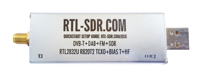
RTL-SDR blog USB dongle. Image source
In this second and final part of my introduction to RTL-SDR I’ll go over the most popular software that is available for use with RTL-SDR dongles. I’ll try to provide a big picture but I’ll be focusing more on what I intend to use in future RTL-SDR projects.
As a software defined radio Hello World of sorts I’ll go over how to demodulate FM signals using a variety of tools. First using specialized software that does the demodulation for us (SDR# and rtl_fm) and then doing the demodulation directly from captured samples of the complex-baseband representation (IQ) using the python scientific computing ecosystem.
This post builds on the concepts presented in the first part of this introduction helping frame them in the context of a real world application.
SDR#
The RTL-SDR blog has a great quickstart guide to get you started with your RTL-SDR USB dongle. If you’re on Windows and follow the SDR# Setup Guide section you should be able to get your generic WinUSB drivers installed and your dongle working with SDR#. This program is a bit of a Jack of all trades when it comes to SDR. With a nice GUI interface it is able to demodulate many different kinds of signals providing you a nice visualization of the power spectral density (PSD) estimate and spectrogram (also known as waterfall) of the output of your RTL-SDR. Below is a screenshot of the program running when tuned for a section of the comercial FM band:
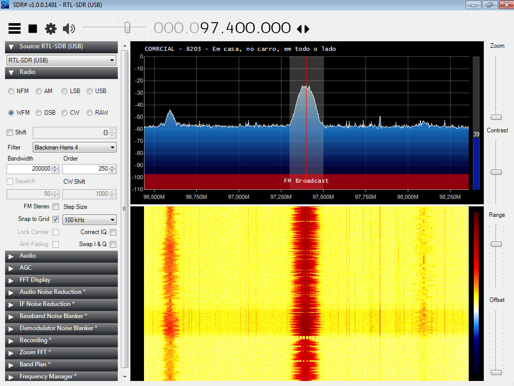
We won’t play around much with this program so I won’t elaborate more, but it’s always nice to have around. Make sure to tune to an FM radio station you like that has a strong enough signal and write down its frequency. I will be using 97.4 MHz throughout this post, the frequency for Radio Comercial here in Lisbon, which has a particularly strong signal where I’m living.
librtlsdr and the rtl-sdr codebase
Most software that interfaces with the RTL-SDR makes use of this library. If you followed the quickstart guide linked above and downloaded SDR#, one of the things it has you do is run a batch file that downloads a pre-build package of this codebase and copies the 32 bit version of rtlsdr.dll to the sdrsharp folder. Sadly it throws the rest of it away so you’ll have to go ahead to the Osmocom rtl-sdr website and download it again if you need the 64 bit version and the command line utilities that come packaged with it. You can either grab the pre-built windows version or build it from source if you’re on Linux (or feeling adventurous).
The rtl-sdr codebase (alternative github mirror), curated by Osmocom is the backbone of the rtl-sdr community. It contains the code for both the rtlsdr.dll drivers (librtlsdr) and a number of command line utilities that use this library to perform a number of functions. Out of these we’ll be mostly interested in rtl_test, rtl_sdr and rtl_fm for now. The following sections will go into detail about each of these tools but for now let us focus on the main library.
The driver relies on libusb (which comes conveniently packed with the pre-built windows version but must be separately installed on Linux) to provide functions to interface with the RTL-SDR dongle. The functions it exports are what allow us to set the RTL-SDR dongle configuration parameters and read IQ samples. Some of these parameters are not exposed directly but are instead set through an internal algorithm. One possible reason for this is that the driver must support RTL dongles sporting a number of different tuner chips while providing a uniform tuner-agnostic interface. To give you an idea of the library’s capabilities, the list that follows details the most relevant (for now) functions that it exports and what their implementations mean for dongles with a R820T/T2 tuner:
- rtlsdr_open/close: opens the device and initializes it/closes the device;
- rtlsdr_get_center_freq/set: gets/sets the center frequency to tune to by configuring the tuner’s PLL based frequency synthesizer to \(f_c + f_{IF}\) (high-side injection);
- rtlsdr_get_freq_correction/set: gets/sets the frequency correction parameter in parts per million (ppm);
- rtlsdr_get_tuner_type: gets the tuner type;
- rtlsdr_get_tuner_gains: gets the list of supported gain values by the tuner. For the R820T this list is hardcoded and was determined experimentally. Its single parameter corresponds to all possible combinations of LNA and mixer gains as the VGA is always set to a fixed value;
- rtlsdr_set_tuner_gain_mode: sets the tuner gain mode to automatic (AGC is used for both LNA and mixer) or manual (gain value is provided manually through the next function);
- rtlsdr_get_tuner_gain/set: gets/sets the tuner gains. For R820T it selects the LNA and mixer gains in order to provide a gain value as close as possible to the provided gain. VGA gain (IF gain) is set to a constant;
- rtlsdr_set_tuner_if_gain: sets IF gain. Unsuported for R820T;
- rtlsdr_set_tuner_bandwidth: sets the tuner bandwidth through adjusting the IF filters. In practice, the list of supported values by the R820T tuner are 6, 7 and 8 MHz or a list of values ranging from 350 kHz to 2.43 MHz. The driver will always round upwards to the nearest supported value. The IF frequency used by the device is determined based on the bandwidth chosen with 4.57 MHz being used for 7 or 8 MHz bandwidth, 3.57 MHz for 6 MHz bandwidth and 2.3 MHz for any smaller bandwidth values;
- rtlsdr_get_sample_rate/set: gets/sets the sample rate of the rtl-sdr output to a value inside the allowed range of [225001; 300000] Hz ∪ [900001; 3200000] Hz. Also sets the bandwidth of the tuner to be the same as the sample rate if it wasn’t set manually before.
- rtlsdr_set_agc_mode: sets the RTL2832U to use digital AGC (not the tuner’s). This seems to amount only to simple fixed gain value being applied;
- rtlsdr_read_sync: reads a fixed number of interleaved 8-bit IQ samples from the device synchronously;
- rtlsdr_read_async/cancel_async: reads asynchronously from the device until cancel_async is called.
It should be mentioned that, as with a lot of useful open source software, there exist a number of forks that seek to tweak and extend the capabilities of the rtl-sdr beyond what the standard drivers allow. Most of these should however be considered experimental. Two examples of such forks are:
- mutability’s: which extends the tuning range of the standard driver via a number of tricks involving manipulating the IF frequency and whether high or low-side injection is used;
- keenerd’s: from the author of the rtl_fm and rtl_power command line tools which includes some modifications to the command line utilities;
rtl_test
We’ll start our exploration of the rtl-sdr command tools with rtl_test. This is an utility that allows you to perform different tests on your RTL-SDR dongle and figure out the allowable ranges for some of the control parameters when capturing samples with your dongle. The following command will capture samples at 2.4 MHz and report any samples lost. You can suspend the program with Ctrl+C and it will tell you how many samples per million were lost:
$ rtl_test -s 2400000
Found 1 device(s):
  0:  Realtek, RTL2838UHIDIR, SN: 00000001

Using device 0: Generic RTL2832U OEM
Found Rafael Micro R820T tuner
Supported gain values (29): 0.0 0.9 1.4 2.7 3.7 7.7 8.7 12.5 14.4 15.7 16.6 19.7 20.7
 22.9 25.4 28.0 29.7 32.8 33.8 36.4 37.2 38.6 40.2 42.1 43.4 43.9 44.5 48.0 49.6
[R82XX] PLL not locked!
Sampling at 2400000 S/s.

Info: This tool will continuously read from the device, and report if
samples get lost. If you observe no further output, everything is fine.

Reading samples in async mode...
^CSignal caught, exiting!

User cancel, exiting...
Samples per million lost (minimum): 0
As you can see it will also report all the supported values for the gain setting of the tuner (see rtlsdr_get_tuner_gains). The PLL not locked message meaning that a lock was not achieved in the frequency synthesizer does not show up when running the program under windows and I’m not sure what causes it. My NooElec RTL-SDR blog dongle is not dropping any samples at 2.4 MHz. You can try different settings of the sample rate with the -s option within the allowable range (see rtlsdr_set_sample_rate above) in order to figure out a maximum safe sample rate at which no samples are dropped (typically 2.56 MHz before the RTL2832U starts dropping samples internally). For instance, trying to sample at the known “unsafe” rate of 2.7 MHz yields:
Sampling at 2700000 S/s.

Info: This tool will continuously read from the device, and report if
samples get lost. If you observe no further output, everything is fine.

Reading samples in async mode...
lost at least 68 bytes
lost at least 68 bytes
lost at least 68 bytes
lost at least 68 bytes
lost at least 188 bytes
lost at least 256 bytes
lost at least 68 bytes
lost at least 188 bytes
lost at least 68 bytes
lost at least 68 bytes
lost at least 68 bytes
lost at least 68 bytes
^CSignal caught, exiting!

User cancel, exiting...
Samples per million lost (minimum): 11
The tuner’s local oscillator frequency can present a significant offset from reality due to the low quality crystal ocillator present in most dongles. Perhaps one of the most useful functions of rtl_test is measuring this error through the the -p option which will report the frequency error in parts per million (PPM) as estimated (I think) from tuning to GSM basestation signals of well known (high) frequency. These frequency errors will vary based on ambient temperature but are otherwise quite repeatable (even inter day). Letting it run for a few minutes should give you a somewhat reliable estimate that you can then use as the frequency correction parameter for other programs such as SDR# or rtl_sdr. The following is the result of running the program with the -p option using my NooElec dongle directly after plugging it in (not warmed up):
$ rtl_test -s 2400000 -p
Found 1 device(s):
  0:  Realtek, RTL2838UHIDIR, SN: 00000001

Using device 0: Generic RTL2832U OEM
Found Rafael Micro R820T tuner
Supported gain values (29): 0.0 0.9 1.4 2.7 3.7 7.7 8.7 12.5 14.4 15.7 16.6 19.7 20.7
 22.9 25.4 28.0 29.7 32.8 33.8 36.4 37.2 38.6 40.2 42.1 43.4 43.9 44.5 48.0 49.6
[R82XX] PLL not locked!
Sampling at 2400000 S/s.
Reporting PPM error measurement every 10 seconds...
Press ^C after a few minutes.
Reading samples in async mode...
real sample rate: 2400188 current PPM: 78 cumulative PPM: 78
real sample rate: 2400164 current PPM: 69 cumulative PPM: 73
real sample rate: 2400190 current PPM: 80 cumulative PPM: 75
real sample rate: 2400153 current PPM: 64 cumulative PPM: 73
real sample rate: 2400151 current PPM: 63 cumulative PPM: 71
real sample rate: 2400153 current PPM: 64 cumulative PPM: 70
real sample rate: 2400159 current PPM: 66 cumulative PPM: 69
real sample rate: 2400177 current PPM: 74 cumulative PPM: 70
real sample rate: 2400157 current PPM: 66 cumulative PPM: 69
real sample rate: 2400163 current PPM: 68 cumulative PPM: 69
real sample rate: 2400150 current PPM: 63 cumulative PPM: 69
real sample rate: 2400197 current PPM: 82 cumulative PPM: 70
real sample rate: 2400155 current PPM: 65 cumulative PPM: 69
real sample rate: 2400144 current PPM: 60 cumulative PPM: 69
real sample rate: 2400165 current PPM: 69 cumulative PPM: 69
real sample rate: 2400150 current PPM: 63 cumulative PPM: 68
real sample rate: 2400169 current PPM: 71 cumulative PPM: 68
real sample rate: 2400166 current PPM: 70 cumulative PPM: 68
real sample rate: 2400164 current PPM: 69 cumulative PPM: 69
^CSignal caught, exiting!

User cancel, exiting...
Samples per million lost (minimum): 0
The results I get from my rtl-sdr.com dongle paint a very different picture owing to it’s much more accurate 1 PPM temperature compensated oscillator. After plugging in the dongle the cumulative frequency error quickly drops to a much smaller value:
real sample rate: 2400001 current PPM: 1 cumulative PPM: 1
real sample rate: 2399958 current PPM: -17 cumulative PPM: -8
real sample rate: 2400060 current PPM: 25 cumulative PPM: 3
real sample rate: 2399996 current PPM: -2 cumulative PPM: 2
real sample rate: 2400014 current PPM: 6 cumulative PPM: 3
real sample rate: 2399948 current PPM: -21 cumulative PPM: -1
real sample rate: 2400026 current PPM: 11 cumulative PPM: 0
real sample rate: 2400005 current PPM: 2 cumulative PPM: 1
real sample rate: 2400072 current PPM: 30 cumulative PPM: 4
real sample rate: 2399939 current PPM: -25 cumulative PPM: 1
real sample rate: 2400011 current PPM: 5 cumulative PPM: 1
real sample rate: 2399996 current PPM: -1 cumulative PPM: 1
real sample rate: 2400017 current PPM: 7 cumulative PPM: 2
real sample rate: 2399950 current PPM: -21 cumulative PPM: 0
real sample rate: 2400030 current PPM: 13 cumulative PPM: 1
real sample rate: 2400010 current PPM: 5 cumulative PPM: 1
real sample rate: 2399982 current PPM: -7 cumulative PPM: 1
real sample rate: 2400030 current PPM: 13 cumulative PPM: 1
real sample rate: 2399995 current PPM: -2 cumulative PPM: 1
real sample rate: 2400004 current PPM: 2 cumulative PPM: 1
real sample rate: 2400019 current PPM: 8 cumulative PPM: 1
real sample rate: 2399954 current PPM: -19 cumulative PPM: 1
real sample rate: 2400013 current PPM: 5 cumulative PPM: 1
I should mention that I get no PPM reports from running rtl_test under windows and again I’m not sure why…
rtl_fm
rtl_fm is a very resource efficient command line tool to capture IQ samples from the RTL-SDR and demodulate FM, AM and SSB signals. For more information on this program make sure to check the rtl_fm guide.
The following command will demodulate and record a wideband FM channel at 97.4 MHz and record it in a file comercial.raw. You can press Ctrl+C to exit after capturing enough samples.
$ rtl_fm -M wbfm -f 97.4M -g 20 comercial.raw
The meaning of the options is:
- -M wbfm: wideband FM modulation;
- -f 97.4M: center frequency of 97.4 MHz;
- -g 20: sets the tuner gain to the closest allowable value to 20 dB (19.7 dB). Without this option present automatic gain is used.
when using -M wbfm a few implicit options are assumed (which can be explicitely overriden):
- -s 170k: for wideband FM a sample rate of 170 kHz is chosen by default;
- -A fast: fast polynomial approximation of arctangent used in demodulation;
- -r 32k: output is decimated to 32 kHz;
- -l 0: disables squelch;
- -E deemp: applies a deemphesis filter.
The output I get running this command and then stopping the execution after a few seconds is:
Found 1 device(s):
  0:  Realtek, RTL2838UHIDIR, SN: 00000001

Using device 0: Generic RTL2832U OEM
Found Rafael Micro R820T tuner
Tuner gain set to 19.70 dB.
Tuned to 97671000 Hz.
Oversampling input by: 6x.
Oversampling output by: 1x.
Buffer size: 8.03ms
Exact sample rate is: 1020000.026345 Hz
Sampling at 1020000 S/s.
Output at 170000 Hz.
Signal caught, exiting!
You might notice that rtl_fm tuned to a different frequency (97.671 MHz) than that we specified (97.4 MHz). This is done to avoid the DC bias that is present in dongles with Zero-IF tuners such as the e4000. This way the dongle is tuned to a slightly different frequency in order to avoid the DC spike and the software later corrects for this in the digital signal processing by shifting the captured signal in frequency to 0 Hz. While this shouldn’t be necessary for R820T tuners one might argue that it’s still justified in case there is any significant flicker noise (1/f psd) or higher power law noises present at the output.
Notice also that the software oversamples by 6x at 1.02 MHz and then decimates the output to the (implicitely) specified frequency of 170 kHz before demodulating. This is because, first and foremost, 170 kHz is not a valid sampling frequency for the RTL-SDR (see the librtlsdr section above for the valid range). 1.02 MHz is in fact the first integer multiple of 170 kHz that fits in the allowed range. But this is not the only reason; in fact if we specifically ask rtl_fm to sample the input at 240 kHz with -s 240k, it will still oversample by 5x at 1.2 MHz despite the fact that 240 kHz is within the allowed range of sampling frequencies of the RTL SDR:
Oversampling input by: 5x.
Oversampling output by: 1x.
Buffer size: 6.83ms
Sampling at 1200000 S/s.
Output at 240000 Hz.
My assumption is that this is done in order to mitigate the quantization noise. Recall that the output of the RTL-SDR is 8 bits and therefore oversampling and decimating in software where we’re not limited to 8 bits should provide a better noise figure than relying on doing the decimation in the chip. Furthermore, it provides greater control over the decimation process, letting the software choose the low-pass filter. From these considerations it would make sense to always use the highest possible sampling rate but rtl_fm is built with limited resources in mind so that might provide a reason for it compromising for sampling frequencies closer to 1 MHz.
rtl_fm stores the raw audio in a file as signed 16 bits integers. To load it in python with numpy you can therefore do:
import numpy as np

raw_audio = np.fromfile("comercial.raw", np.int16)
To listen to it you can always use scipy to store it as a .wav file and then play it in your favourite media player:
from scipy.io import wavfile

wavfile.write("comercial.wav", rate=32000, raw_audio)
Recall that the default output rate of rtl_fm in wideband FM mode is 32 kHz but if you changed that with the -r option make sure to provide wavfile.write with the correct one (and that it is within the allowed range of your sound card…).
Alternativelly you could install and use SoX which is a great program to convert audio files between formats (including raw audio signals), as well as playing and recording them. The following command will play the raw audio file with sample rate 32 kHz, 16 bits signed int encoding and 1 channel on my windows machine:
$ sox -r 32k -t raw -e signed -b 16 -c 1 comercial.raw -t waveaudio
You can replace “-t waveaudio” with a .wav filename to store it in a wav file instead. Make sure to refer to SoX’s documentation for a full description of the options available.
rtl_sdr
Finally, the most general use command line tool in the rtl-sdr package is rtl_sdr. This program will let you capture IQ samples directly and store them in a file (or pipe them into some other command line application):
$ rtl_sdr -f 97400000 -g 20 -s 2400000 -n 24000000 comercial_s2m4_g20.dat
The options in this case mean:
- -f 97400000: sets the tuner frequency to 97.4 MHz;
- -g 20: sets the tuner gain to the closest allowable value to 20 dB (19.7 dB);
- -s 2400000: sets the sample rate to 2.4 MHz;
- -n 24000000: instructs rtl_sdr to capture 2.4e7 samples which should amount to a 10 seconds worth of samples at the given sample rate (10 s * 2.4e6 MHz).
This utility stores the I and Q samples alternately as 8 bits unsigned integers. In order to load them in python we can therefore use something like:
import numpy as np

def load_iq(filename):
    x = np.fromfile(filename, np.uint8) + np.int8(-127) #adding a signed int8 to an unsigned one results in an int16 array
    return x.astype(np.int8).reshape((x.size//2, 2))    #we cast it back to an int8 array and reshape
This will load the file and return an numpy.int8 numpy array with shape (nsamples, 2), the first column corresponding to I samples and the second to Q samples.
A more convenient format to process the data digitally is to load it as complex samples (I + j*Q). Unfortunately numpy doesn’t have a complex integer type so we’ll have to incur in a bit of memory overhead and spring for a numpy.complex64 array which makes it less useful when dealing with a large number of samples:
def load_iq_complex(filename):
    x = np.fromfile(filename, np.uint8) - np.float32(127.5) #by subtracting a float32 the resulting array will also be float32
    return 8e-3*x.view(np.complex64)                        #viewing it as a complex64 array then yields the correct result
pyrtlsdr
pyrtlsdr is a python library that wraps the rtlsdr.dll library functions and provides you an object oriented API to access them. You can install it using pip since I’ don’t think it’s available through conda. You also need to make sure that the rtlsdr.dll is in your python path. If you don’t want to edit it on windows you can always just drop a copy of the necessary dlls into your working folder…
If you want you can access directly the librtlsdr wrapper functions through importing the librtlsdr submodule. You’ll have to initialize a pointer to the device that you then pass to all the librtlsdr functions. In order to open an rtl-sdr device for instance you could do:
from rtlsdr.librtlsdr import librtlsdr, p_rtlsdr_dev

dev_p = p_rtlsdr_dev(None)             #the device pointer
result = librtlsdr.rtlsdr_open(dev_p, 0) #opens device at index 0
                                   #returns an integer < 0 on error
This is however not the intended use of the library. It defines a much more convenient RtlSdr class which stores the device pointer (and a few other useful variables) and wraps all the functions as methods so that a much more pythonic API is exposed. Most of these methods will have the same name as the original librtlsdr function minus the rtlsdr_ prefix (a notable exception being the methods to read the samples). It also defines a few notable properties that can be used to call the get/set methods in a more idiomatic way:
- center_freq;
- sample_rate;
- gain;
- freq_correction;
- bandwidth.
To collect 10 seconds of data with the same characteristics as that we collected with rtl_sdr we would do:
from rtlsdr import RtlSdr
from contextlib import closing

#we use a context manager that automatically calls .close() on sdr
#whether the code block finishes successfully or an error occurs
#initializing a RtlSdr instance automatically calls open()
with closing(RtlSdr()) as sdr:
    sdr.sample_rate = sample_rate = 2400000
    sdr.center_freq = 97.4e6
    sdr.gain = 20
    iq_samples = sdr.read_samples(10*sample_rate)
Demodulating FM
Armed with our new found knowledge of how to capture IQ samples and load them into python we can finally get working on demodulating FM signals. We will first plot the Welch power spectral density (PSD) estimate of the complex baseband representation obtained in either of the two previous sections:
from scipy import signal
from scipy.fftpack import fftshift
import matplotlib.pyplot as plt

#compute Welch estimate without detrending
f, Pxx = signal.welch(iq_samples, sample_rate, detrend=lambda x: x)
f, Pxx = fftshift(f), fftshift(Pxx)

plt.semilogy(f/1e3, Pxx)
plt.xlabel('f [kHz]')
plt.ylabel('PSD [Power/Hz]')
plt.grid()

plt.xticks(np.linspace(-sample_rate/2e3, sample_rate/2e3, 7))
plt.xlim(-sample_rate/2e3, sample_rate/2e3)
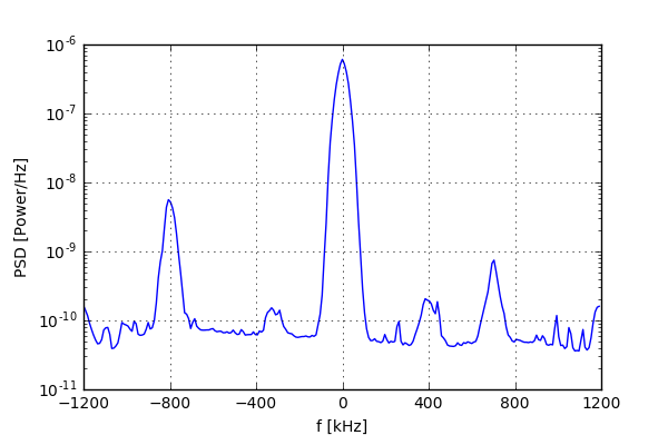
The first thing you should notice is that I have massively oversampled the FM signal. Recall that at a sample rate of 2.4 MHz we’re seeing a portion of the spectrum ranging from 97.4 MHz +- 1.2 MHz. The bandwidth of a comercial FM radio station however is usually around 200 kHz and the two peaks to the left and right of the main one are actually 2 different stations with a weaker signal.
Oversampling the signal we want has an advantage which I touched upon in the rtl_fm section but I’ll reiterate here. Because the RTL-SDR ADC is 8 bit there will be significant quantization noise. Oversampling and decimating in software where the 8-bit limitation doesn’t exist should yield a better SNR figure. I assume that this is the reason that SDR# also samples at 2.4 MHz by default when listening to FM.
As to the other stations, we could have gotten rid of them by setting our IF filter bandwidth smaller. It was automatically set by the driver at 2.4 MHz when we set the sample rate and I chose not to manually set it lower because I wanted these other signals to show up in order to illustrate a point further along. Adjusting your IF filter to the bandwidth of the signal you’re interested in when oversampling is probably a good idea since more selectivity is always good.
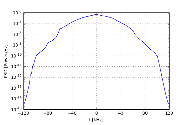
We’re now ready to decimate the signal down to a more manageable rate of 240 kHz which is a bit more than the bandwidth of the signal we’re interested in but makes the decimation math simpler. We’ll let the decimation filter take care of the unwanted stations and out of band noise:
sample_rate_fm = 240000                       #decimate by 10
iq_comercial = signal.decimate(iq_samples, sample_rate//sample_rate_fm)
As you can see the PSD estimate now contains only the signal of interest which is the broadcast by FM station Rádio Comercial:
We can now proceed with the demodulation. Going back to the section on FM modulation of the first part of this introduction we find that in order to demodulate an FM signal from it’s complex baseband representation, it suffices to differentiate the angle of the signal:
In discrete-time this can be accomplished through a differentiating FIR filter. For the sake of simplicity we’ll use the simple forward difference \(\left(1-q^{-1}\right)\) through numpy’s diff function:
angle_comercial = np.unwrap(np.angle(iq_comercial))
demodulated_comercial = np.diff(angle_comercial)
We unwrap the result of the angle function to remove \(2\pi\) discontinuities. Differentiating this angle then yields the desired result with one caveat, the sample rate of the signal is too high for the typical sound card (and effectivelly our ears which in the best of cases can pick up to 20 kHz). A further decimation is thus necessary to bring the signal down to a sample rate that our sound cards can reproduce. 48 kHz is a good value for this as it is supported by most sound cards:
audio_rate = 48000
audio_comercial = signal.decimate(demodulated_comercial, \
    sample_rate_fm//audio_rate, zero_phase=True)
The following is the final result after converting to a 16-bit per sample wav file (for the sake of some compression since 16-bit is more than necessary for a decent audio quality):
audio_comercial = np.int16(1e4*audio_comercial)
wavfile.write("comercial_demodulated.wav", rate=audio_rate, data=audio_comercial)
Tuning to a Different Station
The interesting thing about SDR is that we can do anything with the captured signal. Since we oversampled the signal so much that we actually picked up additional FM broadcasts we can tune into these in software and see if they yield something more interesting.
Recall that multiplying by a complex sinusoid correspondes to circularly shifting the spectrum of the digital signal by that sinusoid’s frequency:
We can use this to center the station 800 kHz to the left of Rádio Comercial which is the frequency for Smooth FM (96.6 MHz). All we need to do is multiply our complex baseband samples by \(e^{j\frac{2\pi}{3}n}\) since \(1/3\) is the required normalized frequency (\(\frac{800\;kHz}{f_s}\)):
f_shift = 800000
iq_shifted = iq_samples*\
    np.exp(1j*2*np.pi*f_shift/sample_rate*np.arange(len(iq_samples)))
We can then decimate the resulting signal in order to obtain the complex baseband representation of the FM broadcast of Smooth FM in the same fashion as we did for Rádio Comercial. The PSD estimate of the 3 signals is depicted next for comparison:
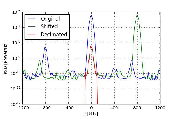
Demodulation can then be done in the same way yielding the following result:
We can see that this example is a bit noisier owing to the roughly 100-fold less power of the received signal. However it’s pretty much still audible which only speaks to the frequency modulation’s noise tolerance.
What we’ve done here is essentially another digital downconversion similar to the one done inside the RTL2832U to get from IF to baseband. We now know how to easily perform these frequency shifts in software and the same principle can be applied for different purposes such as performing a frequency correction directly in software or tuning the RTL-SDR a bit off-frequency to avoid a possible DC spike and then correct for this in software like rtl_fm does.
Up Next
My next posts will be an introduction to GNU radio where I’ll demodulate FM signals in real time and another which will provide a brief overview to the GPS system and sampling of GPS L1 signals. Stay tuned!
Comments !