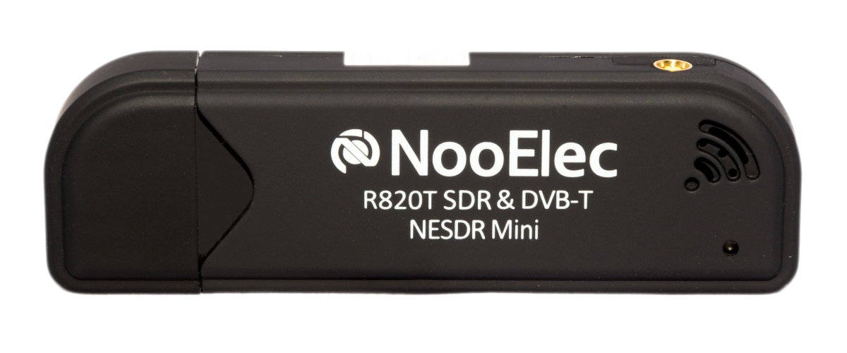
NooElec RTL-SDR USB dongle. Image source
The purpose of this article is to introduce a small and cheap device that is quickly becoming a staple of the modern radiofrequency enthusiast’s toolbox. Initially this two-part introduction to RTL-SDR was meant as a single blog post. I intended to first go through the theory and working principles of the hardware and then move on to the software that I plan to use in future RTL-SDR projects. Finally, I intended to use this software to implement a simple FM demodulator in order to illustrate my points through a practical application.
The more I researched this topic however, the more things I found that I wanted to write about here and this post eventually grew to be too lengthy for a single serving. I wanted this first article to be quite in depth, especially regarding the inner workings of RTL-SDR dongles because I wanted to have a single point to refer back to on this matter, both for my sake and that of any readers out there.
As such, in this first part of my introduction to RTL-SDR I’ll go over some basic principles of telecommunications that I feel are essential in order to understand the working principles of SDR hardware. I will then describe the components that make up the RTL-SDR and explain their functioning.
This means that this first part is mostly theoretical but I hope that doesn’t deter anyone from following along. If you’re not all that interested in understanding how everything works I guess that skipping the Innards of RTL-SDR dongles section should still provide a minimum working knowledge of RTL-SDR going forward. You can always refer back to this post if you need a more in depth understanding further along the path…
Analog Communications 101
Communication systems often involve transmitting a message \(m(t)\) through a pass-band channel, i.e., a channel where only a limited range of frequencies can be used. A good example is comercial FM radio transmissions, usually restricted to a frequency band between 85 and 108 MHz which must accommodate multiple stations, each one being allocated a <200 kHz band. Given that the message we’re interested in transmitting often has support in a different range of frequencies, as is the case of raw audio signals in the human hearing range ([20 Hz; 20 kHz]), the signal must first be shifted in frequency in order to satisfy the requirements of the particular channel of communication.
This is accomplished by modulation whereby one characteristic of a carrier wave (usually sinusoid like \(A\cos(2\pi f_ct)\)) will be made to vary according to the modulating signal: \(m(t)\) (also called the message) producing a modulated signal: \(s(t)=B(t)\cos[2\pi f_ct + \theta (t)]\). There are two main forms of analog modulation:
- Amplitude Modulation (AM): where the characteristic that is made to vary is the amplitude \(B(t)\) of the carrier;
- Phase/Frequency Modulation (PM/FM): where the characteristic that varies is the phase \(\theta (t)\) of the carrier.

We’ll discuss these in the following sections as they help introduce a few points that are important later on but before we move on here’s a useful glossary of terms commonly used in telecommunications:
- Baseband (signal): Signal that has support in a narrow range of frequencies about 0 Hz;
- Passband (signal): Signal that has support in a narrow range of frequencies about a central frequency \(f_c\);
- Bandwidth (of a signal): some measure of the support of a signal in the frequency domain (has many different technical definitions);
Amplitude Modulation
The simplest form of modulation is double sideband amplitude modulation (DSB-AM). As the name indicates, this modulation uses the amplitude of the modulated signal to encode the message to be sent. This is achieved by simply multiplying (or in telecommunications’ lingo mixing) the message with a sinusoidal carrier wave.
In the frequency domain this has the effect of convolving the Fourier transform \(M(f)\) of \(m(t)\) with that of a cosine wave:
which effectively shifts the spectrum of \(m\) to \(f_c\). If \(m(t)\) is a baseband signal, this (up)converts it to a passband signal around \(f_c\) so it can be transmitted through an appropriate bandpass channel.

Demodulating the signal can in theory be done by multiplying again by a sinusoid of the appropriate frequency. This second mixing will shift a copy of the original message back to f=0 and another to a frequency \(f=2f_c\) which can be discarded by low-pass filtering.

On the receiver side however we don’t know the original phase of the carrier, which we will denote \(\phi\), and therefore it’s impossible to align it with the sinusoid generated locally at the receiver end. Introducing this initial phase our received signal can be written as:
The result of our naive demodulation scheme is then:
This is effectively \(\frac{A}{2}m(t)\cos(\phi)\) + a couple terms at frequency \(2f_c\) which are the result of this second mixing. Low pass filtering this signal to get rid of these higher frequency components then yields the desired result with one caveat: the constant factor \(\cos(\phi)\) which in the worst case is 0 when the two waves are in quadrature with each other.
One way to get around this scheme’s limitation is mixing the received signal not only with a locally generated sinusoidal wave \(\cos(2\pi f_ct)\) but also with a second sinusoid shifted 90º in phase: \(-\sin(2\pi f_ct)\). After low pass-filtering this results in:
And since the sine and cosine can’t both be 0 we can always recover our message. An elegant way of doing that is by taking the Euclidean norm of the vector which gets rid of the factor depending on \(\phi\) yielding \(Am(t)/2\). We can also figure out the original carrier wave’s phase from the arctangent of the two components.

It is important to note however that in standard AM the message must first be shifted by a constant C such that \(m(t)+C\geq 0\). This means higher power consumption since we’re “wasting” energy transmitting the carrier together with the message but on the other hand the receiver has access to the original carrier and certain simpler demodulation schemes such as envelope detection are available.
Complex Baseband Representation
What we’ve done in order to demodulate AM is essentially downconvert the modulated signal back to baseband. We realized however that mixing with a single sinusoid does not capture all the information present in the original passband signal but that two not in phase sinusoids must be used. This can be interpreted making use of the fact that Fourier transforms of real signals are in the general case complex functions of frequency satisfying \(S(f)=S^*(-f)\). Mixing a passband signal with a cosine wave will shift the spectrum but kill any imaginary component since the positive and negative frequency contributions will cancel each other out. The same is true for sine waves and real components.
One way to retain full information is then to simply multiply the passband signal with a complex sinusoid \(e^{-j2\pi f_ct}\) which will shift only the positive part of the spectrum back to f=0 avoiding the whole issue.

That’s exactly what we’ve done with our modified demodulation except we disguised it by writing it as a real 2-vector instead:
In fact, given any passband signal \(s(t)\), we can write it in the form:
which implicitly defines its In phase (\(s_I(t)\)) and Quadrature (\(s_Q(t)\)) components (I/Q). It’s complex baseband representation is then defined as:
This is a very useful representation of a pass-band signal since it contains the same information as the original signal but is band-limited by a much lower frequency. If \(s(t)\) has a bandwidth of W around a frequency \(f_c\), then it’s band-limited by \(f_c+W/2\) and therefore, by Nyquist’s theorem, must be sampled at least at \(f_s \geq 2f_c+W\). By contrast, \(s_b(t)\) is band-limited by \(W/2\) and can be sampled and digitally processed at the (usually) much more amenable \(f_s \geq W\).

Alternative ways to write \(s(t)\) as a function of \(s_b(t)\) are:
The last expression makes obvious what we already saw in the previous section about demodulating an AM signal given it’s complex baseband representation. That it amounts to taking it’s complex norm: \(\mid s_b(t)\mid\) (also called the envelope). Likewise, it’s phase \(\angle s_b(t)\) gives us all the information necessary to demodulate any angle based modulation.
We can now represent the same diagram depicting how to obtain the complex baseband representation and reconstruct the original passband signal but in complex notation:

Frequency Modulation
In frequency modulation the message is encoded in the instantaneous frequency of the carrier wave:
Comparing the above expression with the last formula giving the passband signal from it’s complex baseband representation we find that for a frequency modulated signal we have:
We can thus easily find a scheme to demodulate FM signals by converting to complex baseband and differentiating its phase in order to find the instantaneous frequency:

Software Defined Radio
Many forms of radio communication systems were designed with analog technology in mind. Software Defined Radio (SDR) is a communication system where part of the traditionally analog signal processing, accomplished by means of analog electronic circuits is replaced by digital signal processing (DSP, accomplished my means of analog to digital conversion/digital to analog conversion (ADC/DAC) and any form of computers or embedded system running DSP software.
By replacing hardware components with software, through inserting an ADC/DAC as far upstream the signal flow as possible and processing the digital signal instead, very flexible and general purpose systems can be realized since software is much easier to change than hardware components. Ideally, one would place an ADC or DAC directly at the antenna for maximum flexibility but this is not practical and SDR systems typically include a flexible radio frequency (RF) front-end before sampling as in the conceptual diagram below depicting the typical SDR system based on the one that can be found on Wikipedia’s SDR Page:

Note that the term Software Defined Radio denotes the whole communication system including the antenna, any specialized hardware and the computer/embedded system running the DSP. In the following however we’ll (ab)use it by equating it with the hardware that is used to deliver the digital samples to a personal computer since that is the use case we’re interested in.
A Cheap SDR
There are many general purpose commercially available SDRs, both receiver only and receiver/transceiver, but they’re rather expensive in general (>€100 for RX and >€300 for RX/TX). This is where DVB-T TV tuner USB dongles based on the RTL2832U chipset come into play. As the name indicates, these cheap dongles (€10~€20) were meant for receiving DVB-T TV but hacked drivers from Osmocom are able to turn them into wideband receiver only SDRs. This cheap SDR is therefore typically known as the RTL-SDR:
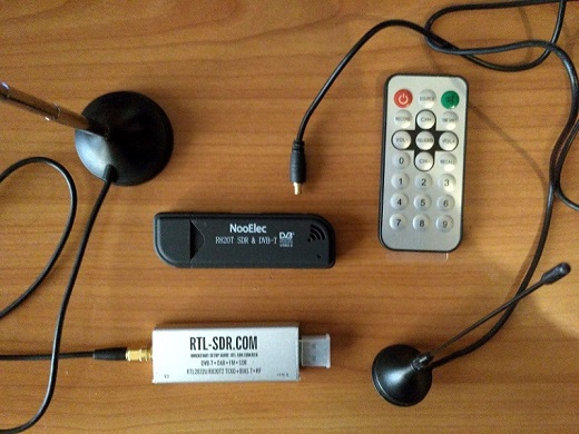
Here you can see the two dongles I own. The one on top looks like a generic DVB-T USB dongle but it was tuned by NooElec for use as a SDR. You can see in the picture the remote that comes with it for its original intended use as a TV tuner. It has a standard MCX antenna connector and comes with a small whip antenna.
The dongle that you see at the bottom is the one sold by the RTL-SDR blog. It comes with several improvements over the generic dongles for use as a SDR. You can read all about these in the the webpage linked. For my intended use of capturing GPS signals I was mostly interested in the software enabled bias-T in order to power an active GPS antenna, the SMA antenna connector and of course the 1 PPM temperature controlled oscillator for more accurate tuning (the passive cooling is a nice plus too since these units tend to run hot when tuning to frequencies > 1500 MHz).
The innards of RTL2832U based DVB-T TV USB dongles
The overall architecture of RTL-SDR dongles is based on a superheterodyne receiver which is a popular design for receivers that must be able to process signals at a wide range of user-selected frequencies, isolating them from other signals and amplifying them. Examples are many conventional AM/FM radio receivers where the user selects a channel by tuning the radio to it’s carrier wave frequency.
A selective enough filter must be applied to the signal coming from the antenna in order to filter out other signals and noise outside the band of interest before demodulation. For the purpose described above it must also have a tunable center-frequency which makes its practical implementation troublesome. Superheterodyne architectures solve this by downconverting first to an intermediate frequency (IF) in which more rigorous filtering and amplification stages can be applied now that the signal is at a fixed pre-specified frequency (see the figure below for a typical setup).

This downconversion is achieved by mixing with a sinusoidal wave of the appropriate frequency generated by a local oscillator (LO). When the user selects a frequency \(f_c\) to tune to, the LO generates a sine wave at either \(f_{LO} = f_c-f_{IF}\) (low-side injection) or \(f_{LO} = f_c+f_{IF}\) (high-side injection, note that when using this frequency the spectrum of the resulting signal will be inverted in frequency). A byproduct of this mixing is that both \(f_c\) and \(f_c\mp 2f_{IF}\) (for low/high side injection respectively) get mixed into the intermediate frequency. The first is the frequency of interest and the other is the so called image frequency.

An initial radio frequency (RF) filtering stage is therefore useful in order to filter out any signal or noise at this image frequency. This RF filter often has a variable center frequency whose tuning is shared with the LO. Another common component of the RF section of the receiver is an amplifier, often called a low noise amplifier (LNA).
While traditionally the intermediate frequency signal processing section was analog, lately, due to the ubiquity of integrated circuits and the availability of micro-processors in many devices (such as cell-phones) the trend has been to handle some of these tasks digitally. In this case, superheterodyne architectures are useful as they downconvert a passband signal that is too impractical to sample (due to their high frequency requiring very high sample rates) into a lower frequency passband signal that is more manageable to sample without aliasing.
In the RTL-SDR dongles the signal is sampled at a low intermediate frequency after an analog filtering and amplification stage and further processed digitally. RTL-SDR dongles contain 2 important integrated circuits (ICs) which implement the different functions of the superheterodyne receiver:
- Tuner: The RF front-end which implements the analog signal processing part of the receiver and is responsible for the downconversion into the intermediate frequency;
- The RTL2832U: Samples the signal and performs additional digital signal processing tasks such as decimation. Also handles USB control.
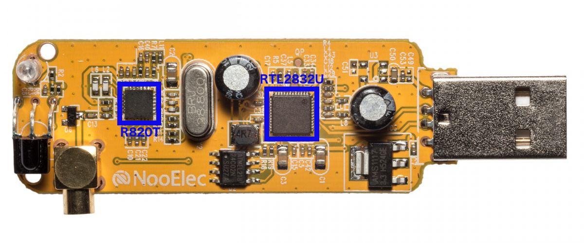
NooElec RTL-SDR dongle opened up. Image source
The following sections will go into details about the function of each of these important components. Information from these sections is gathered from multiple sources including the Osmocom driver’s source code. Superkuh’s website deserves a special mention as it is a veritable treasure cove for anything RTL-SDR related.
Tuner
There are two main families of tuner chips of interest for SDR applications, the now discontinued Elonics E4000 and the Raphael Micro R820T/R820T2 radio tuner which will be the focus of this discussion. The differences between the T and the T2 are small, essentially amounting to slightly better sensitivity¹ for practical purposes.
The datasheet for the R820T was leaked online so a lot is known about the inner workings of this chip. A register description for the R820T2 is also available which details the parameters of the tuner that can be set from outside. A high level simplified diagram based on the one found in the datasheet is depicted next:

The signal coming from the antenna connector first goes through a low noise amplifier (LNA) and is then filtered by a bandpass filter and an image rejection filter. According to the datasheet, the image rejection is 65 dBc.
A fractional PLL based frequency synthesizer generates the LO that is mixed with this filtered signal in order to downconvert it to a low intermediate frequency. The user controls the local oscillator’s frequency directly through the parameters of the frequency synthesizer. This indirectly sets the IF frequency and whether low or high-side injection is used. 3.57 MHz and 4.57 MHz are typical values for the IF of R820T dongles¹ but it’s essentially up to the driver implementation to choose what values to use (subject to the limits imposed by the parameters of the synthesizer and the IF filter).
The frequency range that the RTL-SDR is able to tune to is determined by the range of frequencies that the frequency synthesizer inside the chip can generate. The R820T’s official range found in the data sheet is [42; 1002] MHz with a tuning resolution of 1 Hz but the generally agreed upon real range is [24; 1766] MHz¹ as determined by the RTL-SDR community. In fact, using an experimental set of drivers this frequency range has been extended as far as [13; 1864] MHz with the upper limit having some variability depending on the dongle used.
Finally once at the intermediate frequency the signal is again filtered and goes through a variable gain amplifier (VGA). The IF filter is usually more selective than the RF since that is the point of superheterodyne architectures. In the case of the R820T it is composed of a low-pass filter and a high-pass one that can be configured to have a bandwidth as low as 300 kHz². Its “standard values” however are either 6, 7 or 8 MHz since these are the bandwidths used by DVB-T signals.
There are overall 3 gains in the tuner that can be controlled via external configuration: the LNA, the mixer and the VGA. These gains can be set manually although their precise values are absent from the datasheet. They can also be set automatically via automatic gain control (AGC) in order to optimize the signal to noise ratio (SNR). The LNA and mixer have a power detector at their outputs which is used to control their respective gains for this purpose. The VGA AGC is actually controlled via an analog input port to the tuner which is connected to a power detector in the RTL2832U.
A note on the E4000 chips is that these use a 0 Hz IF so in effect they’re not implementing superheterodyne receivers. This has a notable consequence of producing a DC spike at 0 Hz.
RTL2832U
This is the IC that gives the name to the RTL-SDR dongle. Unlike the tuner, datasheets are not freely available online (you’ll need to sign an NDA to obtain one). A lot of what is known about the inner workings of this chip has therefore been figured out by the RTL-SDR community through reverse engineering.
Realtek’s RTL2832U description states that the chip is meant as a high-performance DVB-T demodulator (with additional support for FM and DAB radio). As such it includes an ADC to sample the IF signal coming from an appropriate tuner, all the specialized DSP required to demodulate DVB-T and a USB controller supporting a USB 2.0 interface. Usage as an SDR takes advantage of a “debug” mode in the chip to deliver the digital complex baseband representation samples directly through USB.
The following high-level diagram represents my best understanding of the functions the RTL2832U is performing when using a non-zero IF:

Initially, the signal coming out of the tuner is sampled by an 8-bit ADC running at 28.8 MHz. No significant aliasing should occur for the low IF values supported if the IF filter is selective enough to kill any strong signals outside its bandwidth.
A digital downconverter (DDC) is then responsible for downconverting the digital signal to complex baseband. The process of obtaining the complex baseband representation is similar to the continuous-time case: mixing with a complex sinusoid will circularly shift the spectrum from IF down to baseband. The signal can then be low pass-filtered and downsampled to get rid of the unnecessary part of the spectrum that was shifted to higher frequencies since the signal of interest is now band-limited by a lower frequency. External configuration parameters inform the DDC of the IF frequency and whether the spectrum is inverted (i.e., if the tuner is high-side injecting).
Finally decimation (using a FIR low pass filter and downsampling) is applied in order to reduce the sample rate of the signal to a value in the range [225001; 300000] Hz ∪ [900001; 3200000] Hz. 2.56 MHz is however the generally agreed upon highest safe sample rate where no samples will be dropped by the chip (they may still be dropped by the USB). This decimation is what usually sets the upper limit on the bandwidth of the sampled signal (unless the IF filter bandwidth is specifically chosen as lower than the Nyquist frequency for the sample rate).
The I and Q complex baseband samples are then delivered through USB as interleaved 8-bit unsigned integers.
A High Level Behavioral Model
It is sometimes useful to have a simplified picture in mind of the RTL-SDR’s internals. This picture, while not perfectly accurate captures the essential behavior of the hardware while hiding some of the complexity. One such behavioral level model of the RTL-SDR is presented next, based upon Lab 6 from Stanford’s Analog and Digital Communication Systems 2014 course:

In its essence, the RTL-SDR provides us a digital complex baseband representation of the signal at whatever frequency band we tune to. Doing away with the added complexity of the superheterodyne architecture, the RTL-SDR’s functioning can be boiled down to:
- Amplification;
- Finding the complex baseband representation through mixing with a complex sinusoid and low-pass filtering;
- Sampling.
These are the essential steps represented in the diagram. The three essential parameters we are able to vary are:
- The gain values (and possible AGC);
- The center frequency we’re tuning to;
- The sample rate which can go up to ~2.56 MHz without dropping samples;
- The bandwidth of the filter which can be chosen anywhere from 300 kHz (making use of the IF filter inside the tuner) up to roughly the Nyquist frequency of the chosen sample rate (where the limiting factor will usually be the decimation filter inside the RTL2832U).
Up Next
The second part of this introduction will introduce the basic software that most RTL-SDR enthusiasts stick to and use it to demodulate FM signals. Stay tuned!
Useful Links:
- rtl-sdr
- Osmocom rtl-sdr wiki
- RTL-SDR subreddit A subreddit dedicated to RTL-SDR. Make sure to check their wiki which is filled with useful information.
- rtlsdr Community Wiki
- superkuh’s website An absolute bible when it comes to the internals of RTL-SDR USB dongles. Tons of useful information, links to datasheets, schematics, etc…
- University of Colorado’s Communications Lab Make sure to check out their lab assignments, particularly Lab 6 which this blog post draws inspiration from;
- Stanford’s Analog and Digital Communication Systems 2014 course Again, make sure to check out the lab assignments for lots of RTL-SDR material;
Comments !